Tufnol materials are suitable for spur, single helical, double helical, bevel and internal gears.
Where Tufnol is replacing an existing bearing, the basic dimensions of shaft and housing will usually be fixed.
Tufnol bearings can range in size from very small machined items to very large bearings fabricated from a number of parts. Moulded Tufnol tubes are produced up to 9 inches (228mm) outside diameter and Tufnol Rolled Laminated tubes are made up to 26 inches (660mm) outside diameter.
Both types of tube in cotton fabric grades have good wear resistance. Moulded tube is usually preferred for bearings, whilst Rolled Laminated tubes are often used for items such as split wear rings, piston rings, and other similar applications, where good concentricity or toughness is required with a thin wall section.
Calculation of bearing sizes should follow the method shown in the following example to ensure that the clearance in the bore is adequate to prevent seizure.
COMPILE AND CALCULATE THE FOLLOWING | ||
Maximum housing diameter | = | A |
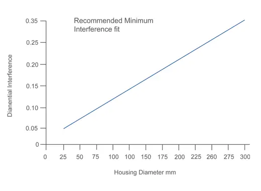
Interference fit (if required) (figure 2) | = | B |
Minimum bearing outside diameter [A+B] | = | C |
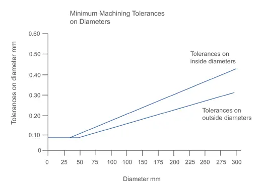
Machining tolerance on bearing outside diameter (figure 3) | = | D |
Max bearing outside diameter [C+D] | = | E |
Minimum housing diameter | = | F |
Maximum interference [E-F] | = | G |
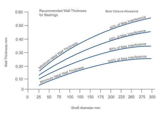
Expected bore closure % (figure 1) | = | H |
Maximum actual bore closure [H% of G] | = | J |
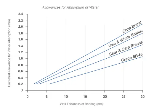
Swelling allowance (figure 4) | = | K |
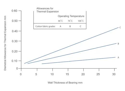
Thermal expansion allowance (figure 5) | = | L |
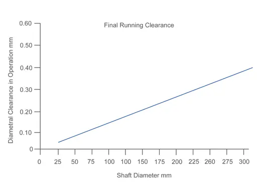
Minimum final running clearance (figure 6) | = | M |
Maximum shaft diameter | = | N |
Min. bearing inside diameter [N + M + L + K + J] | = | P |
Machining tolerance on bearing inside diameter (figure 3) | = | Q |
Maximum bearing inside diameter [P + Q] | = | R |
Note that the variation in bore clearance can be quite substantial when an interference fit is used as it arises from the sum of the machining tolerances on the shaft, housing and the inside and outside of the bearing.
As a result, this type of fit often requires machining tolerances to be the minimum practicable. Some sizes of bush can be machined by a method which allows for an accurate tolerance on wall thickness to be maintained.
However, where a minimum variation in clearance is required, bearings are bored after fitting into the housing.
Figure 1 – Recommended wall thickness for Bearings
Figure 2 – Recommended minimum interference fit
Figure 3 – Minimum machining tolerances on diameter.
Figure 4 – Allowances for absorption of water.
Figure 5 – Allowances for thermal expansion.
Figure 6 – Final running clearance.